")
")
")
")
")
")
")
")
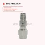
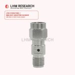
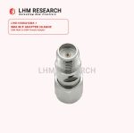
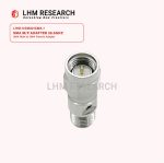
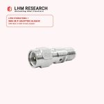
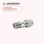
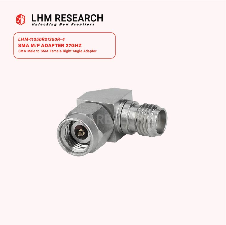
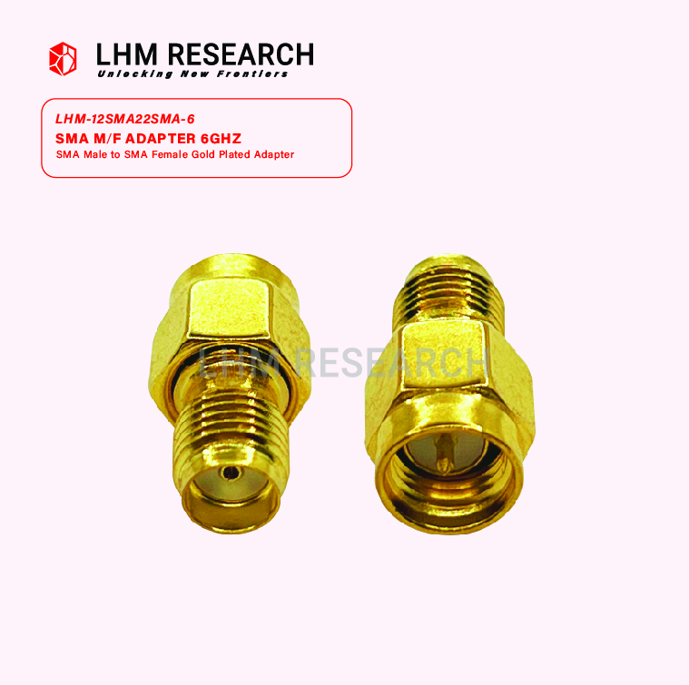
SMA Male to SMA Female Adapter
The SMA Male to SMA Female Adapter – 26.5 GHz is a high-frequency RF connector designed for precise signal transmission and interface conversion. Operating up to 26.5 GHz, it’s ideal for RF test systems, communication devices, and microwave applications.
Constructed from durable brass with gold-plated contacts, this adapter provides low signal loss, excellent durability, and secure connectivity in both lab and field environments.
| Categories | Details |
|---|---|
| Overview | SMA (SubMiniature version A) adapters are precision RF connectors used to connect SMA male and female interfaces. Designed for applications requiring consistent high-frequency performance up to 26.5 GHz, this straight adapter ensures low loss and high reliability in RF systems. |
| Application | RF Lab Testing, Telecommunication Systems, Aerospace & Military, Instrumentation & Measurement |
| Frequency Range | DC to 26.5 GHz |
| Impedance | 50 ohms |
| Insertion Loss | Typically ≤ 0.3 dB |
| Dielectric Withstanding Voltage | 1000 Vrms |
| Operation Voltage | 100 Vrms |
| VSMR | ≤ 1.3:1 |
| Gender | Male to Female |
| Parameter | Specification |
|---|---|
| Temperature Range | -40°C ~ 125°C |
| Parameter | Specification |
|---|---|
| Impedance | 50 ohms |
| Insertion Loss | Typically ≤ 0.3 dB |
| Dielectric Withstanding Voltage | 100 Vrms |
| Operation Voltage | 100 Vrms |
| VSWR (Voltage Standing Wave Ratio) | ≤ 1.3:1 |
| Parameter | Specification |
|---|---|
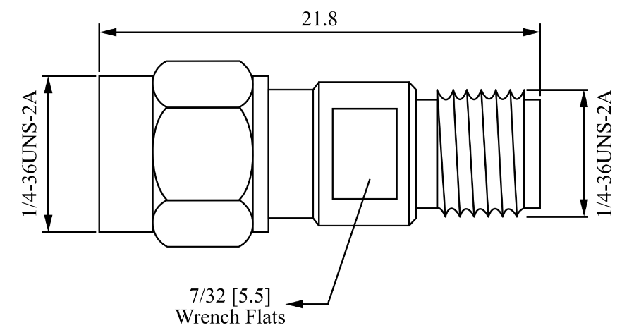
| Total Length | 21.8 mm |
| Weight | 4 g |
| Center Conductor | Beryllium Copper, Gold Plated |
| Body Material | Passivated Stainless Steel Type 303 |
| Insulator | PTFE |
| Connector Type | SMA Male to SMA Female |
| Durability | 500 Cycle Min. |